REACTOR PRESSURE VESSELS: METALLURGY AND FABRICATION
A few brief points will begin this presentation.
-Reactor vessels for light water cooled reactors are manufactured of low carbon alloy steel to secure strength
-These vessels are normally lined with stainless steel to provide corrosion protection against the water used as reactor coolant
-Reactor vessels are difficult, time consuming and expensive to manufacture because of the absolute necessity for near perfection in forming, welding and machining
Let's start off with an examination of the reactor vessel manufactured for the first large commercial nuclear plant in the United States - the Shippingport Atomic Power Station. Below is an illustration - click to enlarge.
 This illustration is taken from a complete Westinghouse-AEC-Duquesne Light Company press release package that was released prior to the dedication of the Shippingport plant (which took place in May, 1958). The details are clearly marked.
 Viewed simply, the vessel has a cylindrical body section, to which on the bottom is welded a hemispherical lower head. The upper head must be removable to allow for refueling or other work inside the reactor vessel; thus, it is bolted to the rest of the reactor vessel. Penetrations for entry of the control rod extensions and instrumentation are obvious. The vessel was roughly 32 feet 6 inches high, 10 feet 6 inches in diameter. The internal height was 375 inches (31 feet 3 inches) and the internal diameter was 109 inches (9 feet 1 inch.) The nominal thickness of the barrel section or wall was 8-3/8 inches.
From the 1958 book "Shippingport Pressurized Water Reactor" written by the Naval Reactors Division of the AEC, Westinghouse, and Duquesne Light, we produce the following passage that introduces us to the metallurgical aspect:
"The vessel is formed of manganese-molybdenum carbon steel plates and forgings (ASTM-SA-302, Grade B) with a 1/4 inch stainless steel (AISI type 304-L) cladding. The 302 material was selected because it was the highest strength carbon steel allowed by code. The weight of the complete vessel, including the closure head and thermal shields, is approximately 264 tons.
"The vessel shell and the bottom hemispherical head were made from plates to which the stainless steel cladding had been roll bonded. These were the thickest clad plates ever roll bonded in the United States."
The book continues to indicate that the top or closure head couldn't be roll bonded, so that the stainless steel was applied by weld deposition (machine welding.)
At the time of construction of this reactor vessel, the ASME codes did not cover reactor pressure vessels; this code was added later. Further information of interest on fabricating the vessel comes from the same book:
"The shell (cylindrical body) is a right circular cylinder formed of three cylindrical courses joined by circumferential welds. Each course, in turn, is made of two semicircular plates joined by longitudinal welds. The longitudinal welds in the three courses were oriented 90 degrees from each other to avoid possible crack propagation." The text continues to indicate that on the top of this cylinder was welded a forged bolting flange (to bolt down the closure head) and that to the bottom was added the lower head, again by welding. The lower head was made from four pie-shaped plates and a central dished or domed section, all welded. The nominal thickness of the lower head is given as 6.2 inches.
We can see that the fabrication of even this first vessel challenged the industry- and vessels didn't get smaller after this but rather got much larger. Before this though let's take a look at a couple of other very early design reactor vessels. Below is the vessel from the nuclear plant built by Babcock & Wilcox for the N.S. Savannah. The illustration is from a book of official specifications for the entire powerplant.

This vessel was fabricated from ASTM A-212 Grade B carbon steel, was clad internally with Type 304 stainless steel. Looking at the illustration (click to enlarge) we see that there are indications for where welds have taken place, seen in the vessel wall and in the head as black wedge shapes. So, we can see that the closure head has a domed section with the bolting flange welded on. We can see that there is a bolting flange welded to the body of the vessel; the body is made up of two cylindrical sections welded atop each other, with a lower vessel head welded on.
As with the Shippingport reactor vessel, coolant enters at the bottom of the vessel and exits much nearer the top. However, note that the Savannah's core was what we call a "two pass" core; coolant passed up around the core basket, down through half of the fuel elements, back up through the other half and then exited the vessel through the outlet nozzles. This vessel for the Savannah had two inlet nozzles and two outlets; the Shippingport vessel had four inlets and four outlets because it was a four loop plant. Only a few very early reactors had coolant entry at the bottom; breakage of a pipe would surely mean draining of the core rapidly. Later vessels had all the pipe penetrations for coolant above the height of the core. Knowing this fact makes it easy to spot very early reactor vessels in random photos.
Just for comparison, let's take a look at the reactor vessel at Indian Point 1. That plant, and the plant for the Savannah, were Babcock & Wilcox's first two commercial nuclear plants.

This is an unusual vessel. Most pressurized water reactors have top entry control rods, but Indian Point 1 had bottom entry. We see, starting at the bottom then, the lower large radius hemispherical head. There are then three cylindrical body sections atop each other; above this is a nozzle ring section, an intermediate top ring and then the bolting flange. The vessel head is bolted down onto this and like the head we saw earlier has a bolting flange section and a domed head.
Let's take a look at some fabrication illustrations before we get into the metallurgical specifics of early vessels.
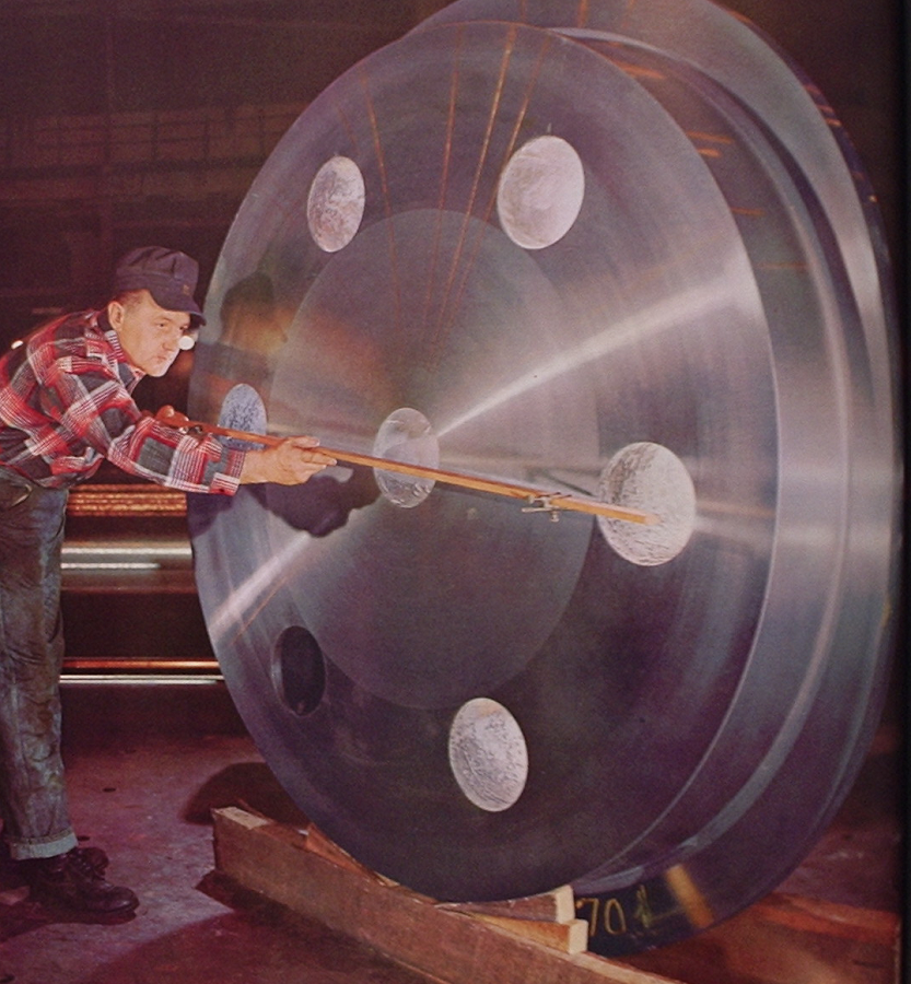
Above, an illustration provided by US Steel for the 1958 Geneva Conference photo book developed for the US AEC, titled "Atoms For Peace - USA 1958." This shows what is described as a three foot thick pressure vessel closure head forged by US Steel for a pressurized water reactor.
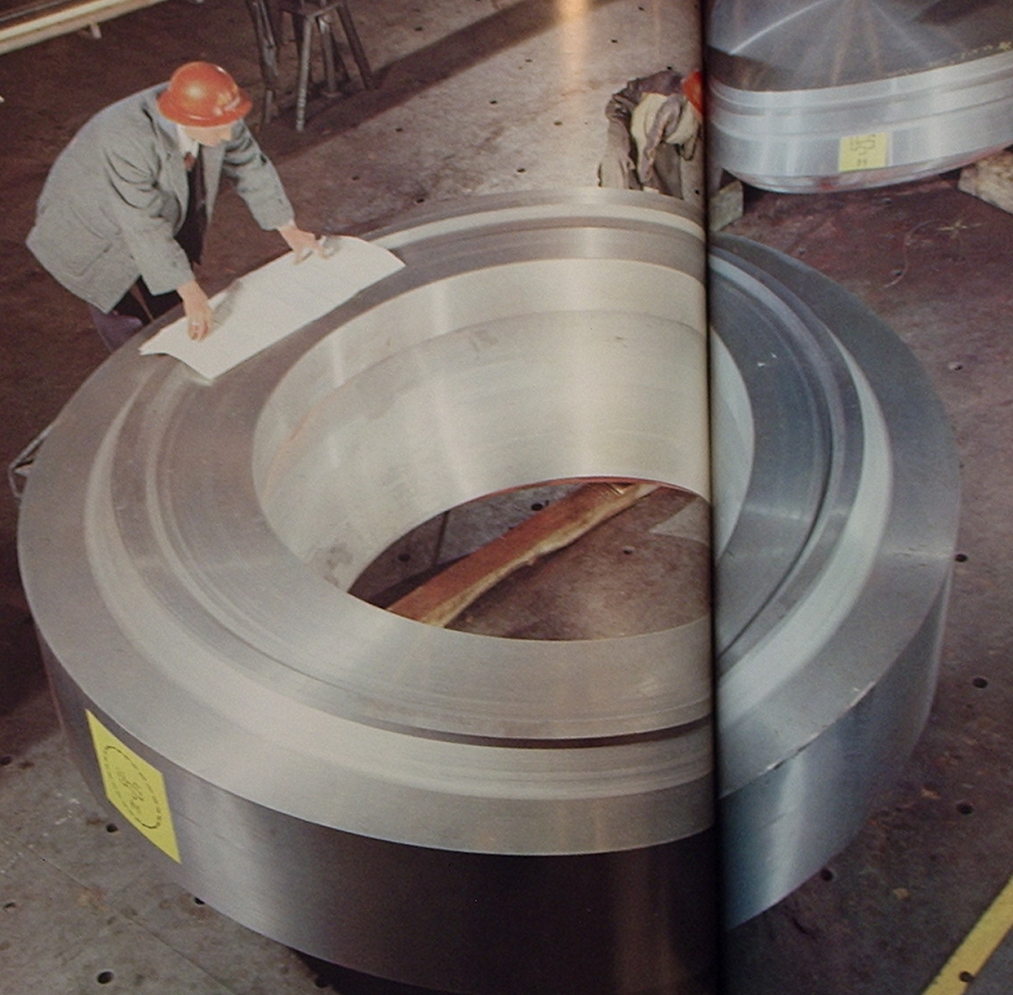
This fascinating illustration shows a bolting flange in the process of manufacture at US Steel prior to being drilled or welded to the vessel. This illustration is from the May 1959 issue of NUCLEONICS and is part of a US Steel ad. There are two parts shown, the bolting flange and a head; the bolting flange weighed 74,000 lbs and the "top disc" or closure head forging seen at top right weighed 36,750 lbs. These parts were forged, then underwent preliminary heat treating and preliminary machining, according to the ad. Following this was quenching and tempering, then ultrasonic inspection, tangential tensile tests, Charpy V-notch impact tests, bend tests and finally magnetic particle inspection. The parts would then be passed along for further machining and eventually fabrication into a complete reactor vessel. The illustration was made at US Steel's Homestead Plant.
We have seen two material specifications mentioned for reactor vessels so far; "Nuclear Reactor Engineering" (Glasstone/Sesonske 1967) points out that these two steels are more properly described as "high strength, low alloy steels" since the normal "carbon steel" description is not specific enough. Following are this volume's stated metallurgical compositions for these two materials:
ASTM A 212-B. Composition, Wt. % Max: Carbon .35, Manganese .90, Phosphorus .04, Sulfur .05, Silicon .30, Molybdenum 0.
ASTM A 302-B. Composition, Wt. % Max: Carbon .25, Manganese 1.5, Phosphorus .04, Sulfur .05, Silicon .32, Molybdenum .6.
Following are some basic specifications for pressure vessel particulars from ASME's "Nuclear Reactor Plant Data" Vol. 1 / 1959:
Dresden 1 used an A 302 carbon steel vessel, clad with 304-L stainless steel; wall thickness was 5-5/8 inches with 3/8 inch cladding additional.
Pathfinder used an SA 212 carbon steel vessel, 'stainless lined,' with a wall thickness of 3 inches.
(Note that boiling water reactors, with much lower pressures, used much thinner vessels - but that as time went on the boiling water reactor vessels became physically much larger than pressurized water reactor vessels.)
From an official brochure covering construction of Connecticut Yankee (Westinghouse PWR) which was ordered in December, 1962 we find that this plant's reactor vessel was SA-302 Grade B with a 10-25/32 inch wall thickness, clad internally with 5/32 inch of 308 and 309 stainless steel. This vessel was 41 feet 6 inches high, and weighed 915,000 lbs dry. This plant's thermal output was 1825 MWt.
NEW MATERIALS
As mentioned in a previous post on this site on Palisades and vessel embrittlement, many years of testing led to issuance of new specifications for reactor vessel materials (and of course, the addition of the ASME Boiler and Pressure Vessel Code, Section III, Nuclear Power Plant Components.) Two new steel specifications were issued for fabrication of vessels:
A533 ASTM Specification for Pressure Vessel Plates, Alloy Steel, Quenched and Tempered, Manganese-Molybdenum and Manganese-Molybdenum-Nickel
A508 ASTM Specification for Quenched and Tempered Vacuum-Treated Carbon and Alloy Steel Forgings for Pressure Vessels.
According to ASTM STP 819 (quoted frequently on this site) "supplemental specifications for A533-B and A508 Class 2 and Class 3 steels limit the maximum copper content to .1% (heat analysis) and the maximum phosphorus content to .012% for best radiation resistance." This is the low-copper alloy change I mentioned in the second Palisades post on this site.
We find in the volume "Toward Improved Ductility and Toughness" (1971, also often quoted on this site) this significant quote concerning the variance of ductility transition temperature with accumulating neutron exposure (for you nuclear types, this is included under 'Increase in Charpy-V 5.2kgm/sq. cm transition temperature as compared to neutron exposure at 288C (neutrons over 1 MeV): "Metallurgical factors may contribute to the observed variance, but variation in composition of residual elements appears to be the dominant cause of the large observed variation in the sensitivity of steels to irradiation embrittlement."
Steel specifications with compositions by weight percent, as tabled in ASTM STP 819, page 66:
A533 Type B Class 1: Carbon .19, Sulfur .20, Phosphorus .008, Silicon .27, Manganese 1.35, Nickel .56, Chromium 0, Molybdenum .55, Copper .07, Cobalt 0, Vanadium 0.
A508 Class 3: Carbon .16, Sulfur .009, Phosphorus .008, Silicon .18, Manganese 1.265, Nickel .68, Chromium .23, Molybdenum .485, Copper .05, Cobalt .01, Vanadium <.005.
We can further briefly compare Westinghouse's official specifications for reactor pressure vessels from 1971 and from the middle 1980's to see the alteration in material including the post-1972 low-copper supplemental specifications as shown below.
1971
A533 Grade B Class 1: Vessel, heads, flanges (plate)
A508 Class 2: Vessel, heads, flanges (forgings)
All surfaces in coolant contact clad with 300 series stainless or with Inconel.
1984
A533 Grades A, B and C Class 1: Vessel, heads, flanges (plate)
A508 Class 3: Vessel, heads, flanges (forgings)
ALl surfaces in coolant contact clad with 300 series stainless or with Inconel.
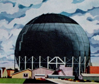
By this time the reactor vessels have become quite large and heavy indeed, especially for the largest offerings from each of the makers. Below is a picture of a very large boiling water reactor vessel being moved out of Babcock & Wilcox's Mount Vernon, Indiana plant.

This is a 1969 illustration of the vessel for Dresden-2. The vessel weighed over one and a half million pounds and was the largest yet built at the time.
The largest range of reactor plants built in the US has been roughly 3400 MWt and around 1100-1200 MWe; we can examine comparative size particulars for vessels from a theoretical study conducted for the NRC in 1977 by United Engineers and Constructors and whose results are contained in reports NUREG-0241 and NUREG-0242.
Westinghouse 4 loop PWR plant 3425 MWt / 1139 MWe pressure vessel: Outside diameter 190.5 inches; inside diameter 173 inches; clad thickness .125 inches; design pressure 2500 psia; design temperature 650F; height 43 ft 10 in; vessel weight 695000 lbs; head weight 160000 lbs (NUREG-0241 Capital Cost: Pressurized Water Reactor Plant)
General Electric BWR plant 3583 MWt / 1190 MWe pressure vessel: Outside diameter 259 inches; inside diameter 238 inches; clad thickness .125 inches; design pressure 1250 psig; design temperature 575F; height 71 feet 6 inches; vessel weight 1,433,000 lbs; head weight 180,000 lbs (NUREG-0242 Capital Cost: Boiling Water Reactor Plant)
Over time, it has been realized that not only are metallurgical considerations of importance, but conditions of fabrication as well. We saw very early on that at Shippingport, the vertical welds on the cylindrical sections were deliberately unmatched when the sections were stacked. In point of fact, vertical welds such as these are problematical at best so that the number of them should be reduced to a minimum. Interesting in light of this was the long standing Babcock & Wilcox practice of manufacturing entire reactor vessel body sections out of a single, gigantic plate which was rolled into a cylinder and then welded right up the side continuously in one pass without stopping by use of a process known as electroslag welding. This ensured that while there would be an axial weld in a region of high exposure, there were not separate circumferential welds. Other manufacturers elsewhere in the world began to use only forgings stacked up to make vessels - but this then incorporates many circumferential welds in the vessel body. Each maker world wide has employed his own methods in making reactor vessels and many have developed proprietary specialty processes.
Pressure vessels have always had a relatively long lead time from order to delivery because of the specialized nature of all parts of the process, from steel plate to finished, tested and accepted pressure vessel assembly. The two major builders of reactor vessels in this country both built large dedicated facilities to make these assemblies; Combustion Engineering built its facility in the late 50's while Babcock & Wilcox built a new large facility in the late 60's. Even with both of these and the addition of Chicago Bridge & Iron (who both shop built and field assembled BWR pressure vessels) orders still fell behind as that late 1960's rush to order nuclear plants took hold, so that by the end of 1969 orders for reactor pressure vessels had been made outside the USA by US vendors to Ishikawajima-Hariwa of Japan, to Rotterdam Dockyard Co. of the Netherlands, and to Societe des Forges et Ateliers du Creusot in France. ("The Nuclear Industry", US AEC 1969.)
By the end of 1971, it was estimated that between Combustion Engineering, Babcock & Wilcox and CB&I that pressure vessels could be manufactured to a total of about 24 per year, with perhaps over 30 per year by 1975. At that time, several orders were also still outstanding for overseas manufacture: Three vessels for GE BWR plants were on order from Japan (Ishikawajima-Harima 2 and Hitachi 1) while for Westinghouse PWR plants 13 were on order (10 from Rotterdam Dockyard, the Netherlands and 3 from Societe des Forges et Ateliers du Creusot, France.) (WASH 1174-71, "The Nuclear Industry 1971," US AEC 1971.) At this time in 1971, the AEC estimated that a nucler plant would have to be ordered six years before the date it could first be made critical; due to the time and production constraints, the reactor vessel had to be ordered five years before startup - or in other words about a year after contract award / plant order. (Only the turbine-generator had to be ordered earlier, immediately at the contract award or "minus six years" date.)
A COUPLE FINAL NOTES
Joseph Talnagi has e-mailed me regarding his work investigating neutron embrittlement as an employee of Ohio State University, which work was done under contract to Battelle Memorial Institute. He notes generally (due to proprietary considerations) that heatup and cooldown rates as imposed at nuclear plants are far more conservative than rates that could realistically lead to brittle fracture. This means that either the amount of damage to the material is often overestimated, or that the inherent self-annealing (mentioned to us by Dave Rossin) has a greater effect than first anticipated. Cores were developed that had much lower neutron leakage (that is, lower neutron flux hitting the pressure vessel) as a further result of years worth of study. Importantly Joseph notes that most data indicates a probable overall reactor pressure vessel life of well over 60 years, perhaps 80 years and maybe even more. He would like me to make the point that the often quoted "40 year life span" for nuclear plants is bunk. A quote:
In your piece it might be good to once again dispel this "40-year design life" canard. There is no "40-year design life". When the first nuclear plants were designed and being planned it was recognized that they would likely operate significantly beyond the 40-year timeline imposed by the economic (not technical) requirement for retiring the debt on the construction bonds that were issued. Since 40 years was what the bond issuers used for fossil plants, the same timeline was assumed for nuclear units. As long as the systems are maintained properly and updated as technology evolves, there is no reason why 40 years should be the limit.
In reference to how some people are using a 40 year life limit on plants and connecting this to reactor pressure vessel embrittlement, this last statement by Joseph Talnagi might be the most significant statement of this entire article.
Here is one final illustration - and it's a look back in time.

This is an illustration from "Atoms For Peace - USA 1958" and shows Combustion Engineering's reactor component shop in Chattanooga, Tennessee in late 1957 or early 1958. We can tell this is an old photo because the vessel assembly in the background has inlet penetrations in its bottom vessel head. Further, later large vessels made at this facility fully occupied the entire width! At lower left we see core barrel and core cage assemblies in progress. A blurred core barrel on a rotary machining fixture (turntable) is visible along the left wall, with more components used in machining and awaiting machining occupying the center of the shop.
I have much more information on reactor vessels, should the need arise. I do believe that this piece, coupled with the two recent Palisades pieces and the older Genkai piece should solidly cover all the basics of reactor pressure vessels in terms of embrittlement, and an introduction to metallurgy and fabrication.
2:15 PM Eastern Tuesday March 6, 2012
ATOMIC POWER REVIEW


It is doubtful whether the US still has the capacity to make these large vessels.
ReplyDeleteSo any future US nuclear renaissance will need foreign help or smaller reactors.
Not a good trend, imho.
Thanks for these historical retrospectives! I've always wondered why aren't these pressure vessels made of/or lined with the same material used for those huge ladles and buckets used to hold molten steel at steel mills. Wouldn't that make for far cheaper vessels that can withstand the heat of total meltdowns? Also, partly off-topic, couldn't submarine reactor designs be adapted for cheaper small scale nuclear plants with a record of reliability and toughness instead of reinventing the wheel?
ReplyDeleteJames Greenidge
Queens NY
Jim, I'd bet that the issue with submarine reactors is that they run on higher enrichment uranium. But I think that smaller rectors are on their way anyway, which is a good thing too - always provided they don't get regulated out of existence.
ReplyDeleteThe higher enrichment for naval reactors is mostly for longer core life. You could use less neutron poison in the fuel load and still use LEU in a small naval reactor -- but you would have to refuel every year or two.
DeleteYou would probably not be able to use fuel enriched to that high of a degree in an economically practical commercial small reactor. Not to say that these won't have some enrichment - but not to the degree of US Navy, or for that matter Russian military or icebreaker cores. Another comment - I don't believe that the metallurgy of those huge steel plant buckets would work at all in a high neutron environment.
ReplyDeleteRe: Another comment - I don't believe that the metallurgy of those huge steel plant buckets would work at all in a high neutron environment."
ReplyDeleteGranted, still, maybe employing such a material as a huge "bathtub" beneath a pressure vessel to catch and hold meltdown slag would effectively nip any "China Syndrome" and ground water contamination concerns in the bud and made clean-up far easier, wouldn't it? Wonder if such an idea was ever considered.
Jsmes Greenidge
@James Greenidge
ReplyDeleteAlready exist in principle, but the idea is to spread out the core over a large area so it can cool down. The picture below show the core catcher on the European Pressurized Reactor.
http://upload.wikimedia.org/wikipedia/commons/7/7a/CHRS_EPR_catcher_flooding.jpg
I have some different ideas in making the pressure vessels. Each vessel manufacturer has employed his own methods in making reactor vessels & many have developed proprietary specialty processes. Which helps in making their brand and products to be apart from others in the market. We are an independent gas company manufacturing and supply pressure vessels for industrial air gases.
ReplyDeleteI am surprised that the pressure vessels aren't lined with a different material. It is just so interesting to me that it takes so much for a vessel to be made. I agree with James though, it seems that there would be an easier way.
ReplyDeleteMia | http://www.bwsfabrication.com/equipment.html